7.3 PI controller design via the root locus
We will now address how to design a controller that compensates for steady-state error. The technique is a straightforward extension of the proportional control technique developed previously with the root locus. However, it requires a bit of motivation, which we will find by studying the steady-state error.
7.3.1 The steady-state error
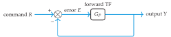
In section 7.1, we introduced the steady-state error, the difference between the command and the steady-state output of the closed-loop system. Let us study this further by examining the error from the unity feedback1 block diagram of figure 7.9. The error is
\[\begin{align} E(s) &= R(s) - Y(s) \tag{7.10a} \\ &= R(s) - G(s) E(s) \tag{7.10b} \\ \Rightarrow E(s) &= \frac{1}{1 + G(s)}\,R(s). \tag{7.10c} \end{align}\]
This is a preview. Read the full book in print or ebook — get it from MIT Press (ISBN 9780262548762).
Instructor with access? Instructor login.